Task Objectives
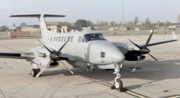
AFD was engaged by a global aerospace integrator to provide design and manufacturing expertise for airframe cleat (aircraft bracket) location tools. This was to aid the integration of a new Intelligence, Surveillance and Reconnaissance (ISR) belly pod onto a special mission business jet.
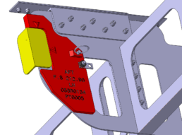
The requirement was to create some new manufacturing tools to aid the accurate positioning of structural cleats that hold the pod in place, across four frame stations.
AFD demonstrated its capacity for innovation and creativity by developing unique solutions for lightweight, cost-effective, and agile tooling. These innovations effectively addressed a complex manufacturing challenge.
Design of Templates
The engineering challenge was for AFD to explore creative tool designs that integrate effectively within the existing airframe structure and enable accurate positioning of the belly pod cleats.
Each tool was designed around existing airframe CAD data and engineered to accurately locate the belly pod cleat onto the applicable frame, using tooling holes and datum faces for reference.
An element of the unique design solution was the incorporation of a detent location pin that was designed to integrate with the existing machined frame tooling hole.
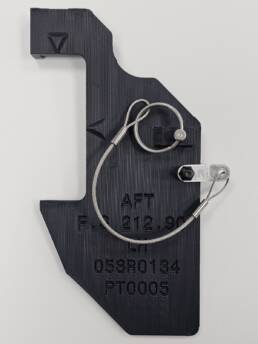
Each tool’s unique part number was printed directly during the manufacturing process, eliminating the need for separate plates, saving on cost, time, and weight.
Manufacturing Approach
The manufacturing approach was aimed at providing a low-cost manufacturing solution for an effective and lightweight cleat location tool, with agile turn-around for both design and manufacturing.
The tools were manufactured using an aerospace standard Stratasys Fortus 450 3D-printing machine, using robust ASA thermoplastic filament (black) and soluble support (white).
The soluble support material is used to ‘support’ the primary ASA material during printing and is subsequently washed away.
ASA is an affordable (medium-cost) material offering excellent UV stability, superior impact strength, and good chemical resistance. The material is a prime choice for tooling applications and for shop floor environments.
Inspection Process
Each 3D printed part was rigorously inspected post-manufacture, to compare the printed geometry with the design intent (CAD model).
A combination of Verisurf and Siemens NX software was utilised to create an inspection report that included a visual display of the tolerances achieved for the part versus acceptance criteria.
Conclusion
The design, scanning and manufacturing of the tools was completed in accordance with customer requirements and within the allocated timeframe.
We thrive on providing bespoke solutions engineered and crafted specifically to help our customers reduce their project lead times and improve their cost-effectiveness.
Providing high quality solutions to complex engineering and manufacturing challenges is what exemplifies AFD.
Testimonial
Head of Production
“We engaged with AFD having successfully worked together on a previous tooling project. For this project we were very keen to trial a novel, agile and affordable method of additive manufacture for lightweight tooling. The option to re-print additional or replacement tools brings additional value to the 3D printing solution.”


