Task Objectives
Airframe Designs was engaged by EIRTECH (EASA Part21J DOA) to provide design support and stress analysis for the installation of an Emergency Locator Transmitter (ELT) system into BOEING 737-8200 (MAX) aircraft.
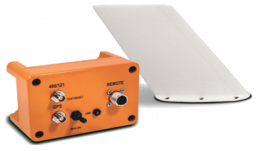
The ELT system constitutes a small blade antenna mounted externally on the fuselage crown, and a transmitter LRU (Line Replaceable Unit) located internally and in close proximity to the antenna.
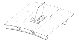
Critically, the antenna requires a feed-through penetration in the fuselage skin in order for wiring to pass between the antenna and the transmitter LRU. Being a blade style antenna, it was also necessary for the installation to provide adequate back-up structure beneath the crown skin to react local bending moments generated from the lateral lifting and fore-aft drag forces acting on the blade.
Structural Requirements
The certification basis for the BOEING 737-8200 (MAX) is defined as CS-25 Amendment 17.
For the external antenna, a static strength assessment was required with consideration to worst case aerodynamic loads generated by the blade aerofoil and a return original strength policy for the skin penetration.
For the Emergency Locator Transmitter (orange item below), the loading is driven by worst case inertia conditions that envelope the crash, extreme manoeuvre, and gust conditions.
Both installations attach to and penetrate Principal Structural Elements (PSEs) that is also categorised as Fatigue Critical Structure (FCS). As such, it was necessary to carry out a fatigue and damage tolerance assessment of the affected parts.
Antenna Installation Design
The design of the antenna installation was essentially split into two aspects: feed-through and doubler reinforcement; sub-structure intercostals for antenna base bending.
For the feedthrough, an external reinforcing doubler (riveted) was sized to return the original strength of the skin.
Considering the aircraft airspeed envelope, worst case lift and drag loads acting on the blade were derived. These loads were then transferred to the sub-structure intercostals and ultimately into nearby stringers.
Fatigue Assessment
The damage tolerance evaluation for the antenna installation focussed on the skin penetration and riveted joints connecting the reinforcing doubler to the surrounding skin.
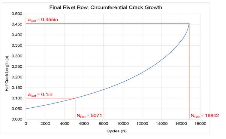
A traditional crack growth analysis was undertaken to determine threshold and repeat inspection intervals for the feed-through and final fastener rows in both the longitudinal
and circumferential directions of the fuselage.
Instructions for continued airworthiness (ICAs) were then published that defined both inspection methods and periods.

Testimonial
(Keith McKercher – Director of Engineering)
“It was important for EIRTECH to create an optimum design team for this high-profile project. The level of scrutiny from EASA was intensified owing to the problems that have plagued the MAX aircraft. From past experience, involving AFD from the out-set was a ‘no brainer’ for such a complex structural installation. They impressed from start to finish!”.
Photo Gallery