Task Objectives
Airframe Designs was engaged by RAS Interiors to compile the static strength substantiation for a bespoke BOEING 737NG Windscreen Stowage.
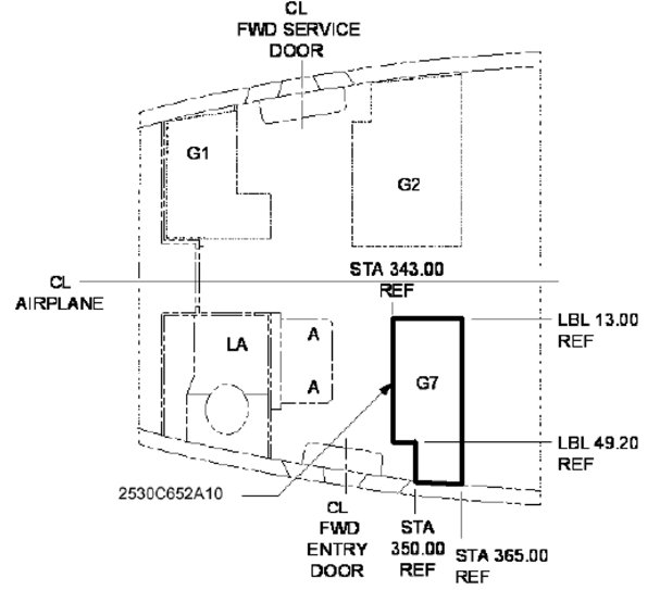
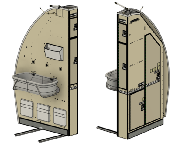
This particular interior monument is designated the G7 by BOEING and is located at the forward entrance to the passenger cabin, hence the description of ‘windscreen’ which is one of its functions.
The objective was to demonstrate that the monument (unit) met all of the necessary airworthiness regulations pertaining to static strength and according to the aircraft original Certification Basis of JAR 25, Change 13, per the aircraft Type Certificate Data Sheet (TCDS) designated EASA.IM.A.120. The monument is a composite unit constructed from SKYCORE phenolic glass fibre faced sandwich panels with NOMEX core.
Finite Element Modelling
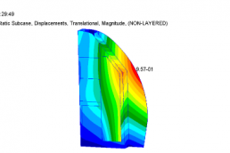
A Finite Element Model (FEM) of the unit was prepared using MSC software (NASTRAN solver) with panels represented using layered shell elements with PCOMP properties.
The model was loaded by critical design inertia cases (9g FWD & 3g SIDE Emergency Landing Conditions / UP and DOWN Gusts) and critical passenger abuse cases per EASA CM-S-009.
Static Strength Substantiation Case Study
The strength of the carcass (panels) was processed using the MSC software. Panel facings were checked against the Tsai-Hill composite failure criterion. The panel NOMEX core was checked for through thickness shear using HEXCEL allowables.
Metallic reinforcing blocks bonded and fastened into the composite carcass were analysed using hand calculations in MATHCAD, balancing the interface loads back into the unit. Items of mass such as emergency equipment, the baby bassinet, and stowage accessories were all assessed separately to ensure adequate retention.
Interface Loads Analysis
The FEM included spring elements at the interfaces between the Unit and the Airframe i.e. the upper tie-rod and lower seat track fittings. These springs had stiffness properties to represent that of the airframe structure.
Ultimate Interface Loads were extracted from the FEM and compared with allowable interface loads per the OEM D6 specification, inclusive of the 1.33 wear and tear factor per EASA CM-S-002.
Testimonial
(Kevin Hann – Head of Design)
“We awarded the project to AFD owing to their extensive experience and knowledge in analysing this kind of structureand their pro- active approach to resolving technical difficulties often encountered in the design phase. The added value of using AFD was their pre-existing relationship with our customer (the DOA) enabling AFD to compile, checkand verify the structural substantiation”.
Photo Gallery