Task Objectives - Allowable Damage Assessment
Airframe Designs was engaged by Draken Europe (EASA Part21J DOA) to carry out an allowable damage assessment for the under-wing pylons and electronic release unit (ERUs) utilised by Dassault Falcon 20 aircraft.
Operating in a maritime environment with low level flying operations over the sea, combined with the use of aluminium alloy materials that are highly susceptible to corrosion, led to excessive damage to the pylon and ERU structures. The level of damage was outside of the Structural Repair Manual (SRM) limits for repair.
The purpose of the assessment was to define allowable damage limits and repair procedures to permit continued and extended use of the pylon and ERU structures.
This was to avoid a very expensive replacement scenario that would also interrupt on-going contracts for which the availability of serviceable pylons was paramount.
Allowable Damage Assessment Case Study
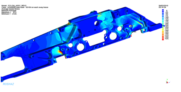
To determine the ‘Allowable Damage’ it was first necessary to establish the static strength of the baseline structure and the level of excess strength / material in the design for the loads experienced within the flight envelope.
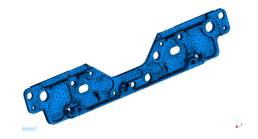
Finite Element Models (FEM) simulating the structures were assembled in MSC NASTRAN using TET10 solid elements. The ERU mesh is illustrated to the side:

The loads for the pylon and ERU had to be understood via historical 3rd party design reports that covered store clearances for various payloads.
The FEMs were then loaded and constrained appropriately, considering the actual degrees of freedom available at each structural interface, and executed in MSC NASTRAN.
The static stress output from each model was then used to evaluate regions of high and low stress to determine areas where material loss was viable.
Allowable Damage Limits
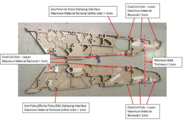
Damage limits were derived by examining local stress fields in conjunction with the baseline material cross-section. The objective was to ensure that after material loss and blending, local regions still had the ability to react all necessary loads.
It was also important to avoid the introduction of any undesirable features or stress raisers and to maintain the original primary load paths. The Allowable Damage limits were defined pictorially.
Testimonial
(Kirk Myers – Head of Design)
“We partner with AFD because of their track-record in simplifying potentially complex tasks into a series of simple steps leading to a pragmatic outcome and completion on time. As a partner, AFD are an integral part of our DOA”.
Photo Gallery