
Task Objectives
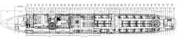
Airframe Designs was engaged by STC Twenty One (EASA Part21J DOA) to carry out fatigue and damage tolerance assessment per JAR 25.571 to support the introduction of a VIP interior into an AIRBUS A330-200 aircraft.
The objective was to assess the impact of modifications to the baseline primary structure to determine if any additional maintenance actions (inspection tasks per JAR 25.1529) were required to ensure continued airworthiness of this airframe.
Evaluation Approach
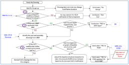
The flow chart explains the F&DT evaluation approach that was taken to substantiate each modification drawing. Over 100 modification drawings were assessed, crossreferencing to the Structural Repair Manual (SRM) to identify if the impacted structure was a) Primary Structure and b)Fatigue Critical Structure (FCS).
FCS is structure that is susceptible to fatigue cracking that could eventually lead to a catastrophic failure of the airplane.
Steps were taken to identify any active repairs in the SRM that could be used to justify the modifications being introduced.
For modifications not covered by active SRM repairs it was necessary to establish the F&DT lives of the baseline structure by reference to relevant maintenance planning literature and thereafter adjust the inspections to suit the modified structure.
Fatigue Evaluation
Frames and Stringers were affected by changes in fastener fit and over-sized fasteners, both of which can have a significant effect on fatigue life.
The fatigue evaluation for such changes followed a conservative approach of deriving knock-down factors for the Repeat Inspection Interval (RII) to derive revised threshold
inspections, considering:
• Life factor due to type of fastener
• Life factor due to size of the fastener hole
• Life factor due to stress concentration of the fastener hole
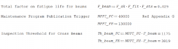
Floor Beams were affected by new Hi-Lok fasteners in the beam flanges. The fatigue threshold requirement was estimated by factoring the existing threshold for rivets in the beam web.
Damage Tolerance Evaluation
The modifications to the Frame and Stringers had no effect on local load distribution, crack propagation or residual strength but did impact on the detectable crack sizes (inspectability).
Consequently, it was necessary to mandate that new structure installed to Frames and Stringers must be removed when conducting inspections of the aircraft structure.
For the Frames and Stringers, the Repeat Inspection Interval was capped to the threshold inspection period calculated by the fatigue evaluation as this conservatively limits the level of cracking to a small crack length at the time of inspection.
For the Floor Beams, the inspection requirements were adequately covered by the RII of the existing maintenance program.
Conclusion
The design, scanning and manufacturing of the tools was completed in accordance with customer requirements and within the allocated timeframe.
We thrive on providing bespoke solutions engineered and crafted specifically to help our customers reduce their project lead times and improve their cost-effectiveness.
Providing high quality solutions to complex engineering and manufacturing challenges is what exemplifies AFD.
Testimonial
Alastair Erskine-Head Of Production
“AFD had already successfully contributed to this VIP upgrade with the substantiation for a Galley Complex relocation so it was a natural step to invite AFD to undertake the overall fatigue and damage tolerance assessment, covering all installations. The methods proposed by AFD used expert knowledge from a former AIRBUS F&DT specialist and followed a logical and easy to follow workflow that enabled efficient approval from both the customer and the authority.”